Ignition

In the days when machines like mine were designed and built, the era of electronic ignition had not yet dawned on us, or was just about to do. Therefore, the ignition systems were quite a bit different than from today’s electronic ones.

On racing bikes it was normal to run a battery powered total loss system, meaning there was no generator or alternator to charge the battery. One would just start the race with a freshly charged battery and hope that the charge would last you through the race. Which it always did. The battery power is routed over the primary windings of the ignition coil and then over something called the breaker points. When the breaker points are closed they allow a magnetic field to be built in the ignition coil. When the breaker cam, which is usually driven by the camshaft, opens the breaker points, the magnetic field collapses and a high voltage output is produced in the coil’s secondary winding – sending 25000 volts or more to the spark plug which then ignites the air/fuel mixture in the cylinder.

The capacitor (Condenser) has two functions. Its main function is to form a series resonant circuit with the ignition coil. During resonance, energy is repeatedly transferred to the secondary side until the energy is exhausted. As a result of this resonance the duration of the spark is sustained and so implements a good flame front in the air/fuel mixture. The capacitor, by default minimizes arcing at the contacts at the point of opening. This reduces contact burning and maximizes breaker point life.

The above arrangement is good for e.g. a single cylinder engine or a parallel twin cylinder engine where the pistons move up and down together. Then a single breaker point is sufficient and the spark plugs will fire together every 360 degrees of crankshaft rotation. Theoretically, the spark plug should set fire to the air/fuel mixture when the piston is at its very top position and just about to start moving downwards on its power stroke. In reality however this is not the case. In order for the maximum cylinder pressure to build up in time for when the piston starts moving downwards, the air/fuel mixture must be ignited BEFORE the piston reaches it top position in the compression stroke. This is called to retard the ignition and was in the old days done by fitting the breaker cam to a shaft concentric with its drive shaft and equipping it with flyweights and springs to allow a mechanical retardation of the cam relative to the breaker point cam follower. Typically, the retard mechanism was designed so that the retard angle was at around zero at 0 – 1000 rpm and then gradually increasing with the rpm to reach 30-35 degrees at 6000 rpm. The higher the engine rpm the sooner the air/fuel mixture needs to be ignited, simple as that.

Enter the electronic age and now we can buy many different makes of electronic ignition systems. I am counting to at least 4 different makers in the UK alone and I see others made in other countries as well. Now, how can we allow modern electronic ignition systems on a vintage racing motorcycle? I guess the answers are that 1) it is almost impossible to see that an electronic system is fitted and 2) the electronic systems are more accurate than the old types and will therefore both a) produce more engine power and b) help us avoid burning holes in pistons due to incorrect ignition retard settings.

The breaker points and cam have been replaced by electronic components, either a coil and magneto or a Hall Effect Sensor. In my case, the sensors ( I have to have 2 each because of my crankshaft layout ) will be located on the crankcase and the triggers ( magnets on the crankshaft, either on the drive belt sprocket or behind it. I just don’t know yet. When the trigger passes over the sensor a small electric pulse is created which is sent up to the “black box”. In here the functions of the breaker points and ignition retard mechanism are taken over by electronic components and the black box interrupts the magnetic fields in the ignition coils at the very right moment, depending on engine rpm, to produce a nice tick-over at low rpms and maximum power at higher. I also assume that the battery will be a small Lithium-Ion job that can be charged via a USB connector. Below I have illustrated the various strokes of a four stroke engine and the sequences of those strokes in a parallel twin cylinder engine – depending on the layout of the crankshaft. Just to illustrate the talk above about the number of points (triggers/sensors) required for the different crankshaft layouts.

The first is the traditional British parallel twin with a 360 degree crankshaft.

The next is the typical Japanese parallel twin with a 180 degree crankshaft.

The third is an engine with a 90 degree crankshaft. This layout reduces engine vibration compared to the other. In the example I have drawn a 90 degree power stroke staggering and that it also creates a “big bang” power delivery. In fact, this is a layout that is adhered to by some Formula 1 engine builders today. It is supposed to provide better acceleration due to the “big bang effect”. However, my NRE has a 90 degree crankshaft as well but a power stroke stagger of 270 degrees as shown in the fourth example below.

TDC = Top Dead Centre – which is when the piston reaches the very top position

BDC = Bottom Dead Centre – which is when the piston reaches the very bottom position.

For those of you that cannot get enough knowledge I have copied a very interesting article, by Vic Willoughby, on the 90 degree crank layout of my NRE engine:

The late Phil Irving could hardly have wished for a more loyal disciple than Ron Valentine, best known in motorcycling circles as designer of the highly successful Weslake racing engines. More than 30 years ago nobody was quicker than Valentine to recognize the merit of Irving’s proposed cure for the engine vibration that, in varying severity, had long plagued Britain’s big four-stroke parallel twins, condemning their riders to mobile vibro-massage without the option.

The essence of Irving’s brainwave was to replace the standard crankshaft with its crankpins in line, by a shaft with its pins staggered so that when either piston is at top dead centre (where it primary inertia force is greatest) the other is approximately at midstroke and generating no primary force. This arrangement considerably reduces the engine’s maximum inertia force, and thus vibration – though not by so much as the 50% one might suppose, as we shall see later.

A second benefit stems from the fact that when either  piston is stationary at tdc, the other is moving at or near its maximum speed and thus contributing to the flywheel effect, so that the flywheels themselves can be a bit lighter for the required level of smoothness. It was this consideration that dictated Irving’s original choice of 76° for the spacing of the crankpins. For with that angle – given that the centre length of most connecting rods is near enough four times the crank radius – when either piston is at TDC, the “big-end” angle (con-rod to crank) in the other cylinder is a right angle, hence piston speed highest.

To their shame and perhaps because of an irrational

horror of uneven firing intervals? – the manufacturers of even the most vibratory parallel twins showed not the slightest interest in Irving’s proposal despite the relative ease with which they could have converted an engine for test by twisting the crankshaft and camshaft, adjusting the spark timing and fitting a second carburettor where necessary to obviate a mixture bias from overlapping induction phases.

Following the demise of the British industry, it eventually fell to Ron Valentine (and his assistants, including mathematician Tom Oliver) to prove the soundness of Irving’s scheme when (three or four years ago) they completed their second 76° crankshaft for Steve McFarlane’s 952cc (80.5mm x 93.5mm) BSA parallel twin classic racing sidecar outfit. Stretching both bore and stroke of the original A65 engine had aggravated its vibration to the point where the crankcase was in danger of disintegration.

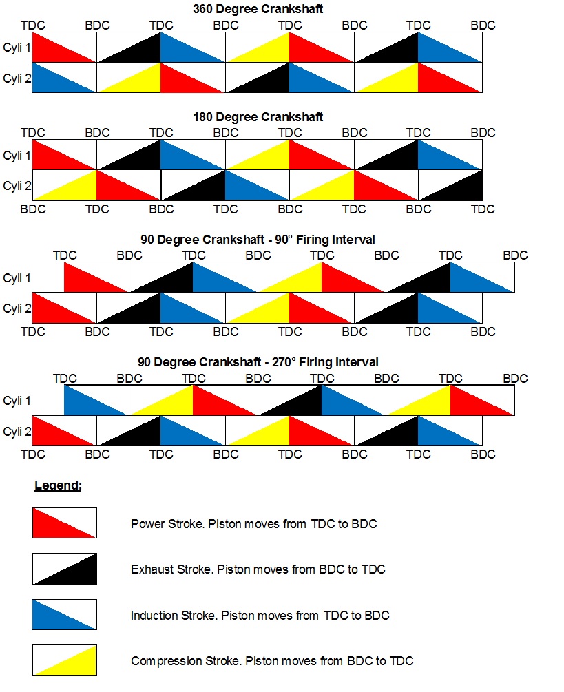
Machined from a solid bar by Dave Nourish, Nourish Racing Engines (NRE), in his Oakham workshop, the new shaft proved to require balancing (to a factor of 50%) as if it were two separate flywheel assemblies joined together. Once that was done, the engines character was transformed. Gone were the frantic shakes. Instead, said McFarlane, there was a slow and lazy throbbing sensation as – to the accompaniment of a pleasant off -beat exhaust lilt, reflecting the 436°/284° firing intervals – the revs soared to 7,000 RPM and the more powerful 1000cc – 1200cc Imp engined outfits were humbled as the BSA won its heat in the Snetterton Race of the Year meeting in 1990.

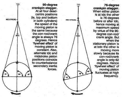
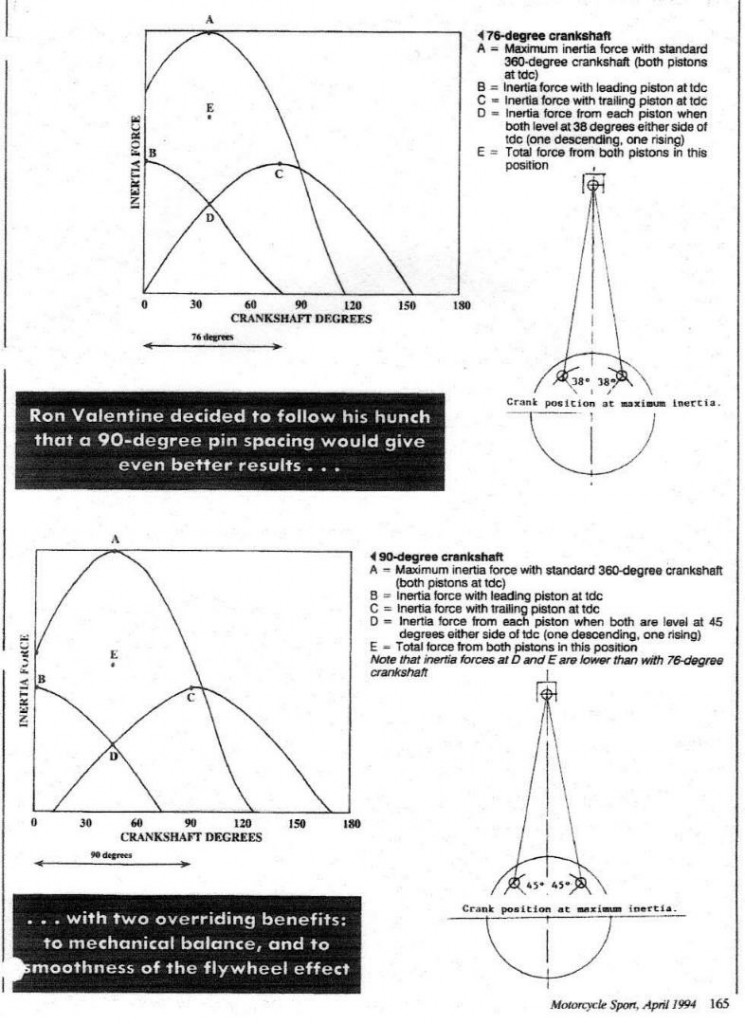
Encouraged that his and Nourish’s sacrifice of valuable time and effort had proved worthwhile, Valentine decided to follow his hunch that a 90° pin spacing would give even better results. True, the instantaneous contribution of the descending piston to flywheel effect, while the other was at TDC, would be slightly reduced because it would be just past its maximum – speed position (big-end angle only76°, not 90°) but there would be two overriding benefits – one to mechanical balance, the other to the smoothness of the flywheel effect.

Balance would be enhanced because the top and bottom dead – centre positions of either piston (where the secondary inertia forces act upward) would coincide with the midstroke positions of the other, where the secondaries act downward. Thus those forces would counterbalance one another at the cost of a small rocking couple.

As to the moving piston’s contribution to the flywheel effect, this would be the same whether the stationary piston was at TDC or BDC (the big-end angle being 76° in both cases). With the earlier 76° pin spacing the ideal “big-end” angle of 90° was achieved only when the stationary piston was at TDC. When it was at BDC and the moving piston was rising, not descending, the angle was only 62°, so the effect was not constant but fluctuated at high frequency. Of these two benefits in favour of 90° pin spacing, the absence of unbalanced secondary forces is clearly the more significant.

When the subject of “cranky cranks” was discussed in Motorcycle Sport three years ago Charles Bulmer suggested that a 180° crankshaft would be even better provided its primary rocking couple were eliminated by means of a crankshaft-driven contra-rotating balance shaft. Quite so, for an engine so designed from scratch by a manufacturer, as with some Hondas.

But what Phil Irving was proposing was the least possible alteration to already established mass-production lines to overcome a serious deficiency in British parallel twins. Given a clean sheet of paper, he had long since shown his own preferences for twin cylinder four strokes: designed just before the second world war, his 600cc Velocette Model 0 vertical twin was a model of smoothness; like its racing stable mate, Harold Willis’ 500cc super-charged “Roarer”, it had contra-rotating geared crankshafts and shaft drive. Later, his postwar 50° V-twin Vincent Rapide ranks as one of the industries greatest designs.

Again drawn by Ron Valentine and machined by Dave Nourish, the 90° crankshaft has four flywheel discs and is a replacement for the conventional (360°) shaft in one of Nourish’s Westlake powered classic racing 500cc NRE Triumph based pushrod parallel twins. Since the total upward inertia force with the standard crankshaft occurs when both pistons are at tdc together, it might be supposed that separating the TDC positions by means of staggered crankpins would halve the force and double its frequency, regardless of whether the stagger is 76° or 90°. Not so as Mr. A Archdale was at pains to confirm in the original “cranky cranks” discussion, although the individual TDC forces in each cylinder remain one half of the total for the 360° shaft, the total upward force occurs when both pistons are level and their cranks equally disposed each side of TDC, i.e., 38° before and after TDC for the 76° stagger and 45° for the other. The point one must grasp here is that – although one piston is moving upward and the other downward when they are level – their inertia forces are both upward, as can be seen in the accompanying curves, where both points are above the base line. Note too that the 45° points are slightly lower on the curves than the 38s, indicating a slightly lower force in favour of the 90° pin spacing.

The net result, as calculated by Valentine and confirmed by Bulmer, was that whereas the 76° shaft reduces the maximum upward inertia force by a useful 32%, the 90° shaft is an altogether better proposition with a reduction of almost 45% (see Tom Oliver’s graphs)

The first tentative outing for the “90” was at Mallory Park last May, when Martin Smith found the engine considerably smoother than standard. It was also 4-5 bhp up in power as a result of new cam profiles – Valentine had replaced the Triumph type radiused tappets by experimental roller cam followers, since they are less dependant on copious lubrication, and had taken the opportunity to up rate the cams.

In the Classic TT Robbie Allen was in the hot seat and finished 10th in the 500cc race, eighth in the unlimited. However, in common with most classic racing participants, Robbie is well over the win-or-bust age range and the object of the exercise was not to win but to compare the modified crank with the standard one. Riding apart, the fact that Robbie’s bike finished well ahead of a brace of standard NRE’s reflected the cam changes rather than the pin spacing. Subsequent bench tests at Oakham gave a repeatable 57-58 bhp at 9,000 RPM and a one off flash reading of 62.5 bhp at 9,800 RPM.

Since riders with an analytical flair of a Geoff  Duke, John Surtees or Peter Williams are as rare as elephants teeth, Nourish had intended to try the machine himself  at Jurby airfield but was foiled by atrocious weather. Before the final outing (to the Manx GP) however, he took it to East Kirby airfield, in Lincolnshire, for assessment and was delighted by the extent of improvement. A few other invited riders were equally impressed. Alas in the Island, Allen was troubled by a few unrelated problems – valve float and missed gears –  before an ignition failure in one cylinder brought about his retirement in the third lap. But Nourish is now so hooked on the new crankshaft that he is planning to market complete 90° NRE engines.

Conversion kits for other engines, however, would not be a commercial proposition. Each 90° shaft, says Dave, is suitable only for the precise reciprocating weights of its particular engine – and con-rod weights, for example, vary enormously (the top portion is the critical end), so the balance holes in the flywheel discs must vary too. There are other relevant variations and the net result is that machining a shaft to suit a particular engine would take too much costly time.

Engine vibration is unpleasant in touring machines as well as racers. Some tourists may dismiss a mild case as inevitable provided they don’t make day long trips – or try a BMW boxer and realize what they are missing. In racing, however, it is unforgivable, especially in long distance events such as TT races. It can cause not only metal fatigue – breaking anything from brackets to engine plates – but also rider fatigue. It can impair engine performance by seriously upsetting carburetion. And, at best, it must absorb a modicum of power. Phil Irving now has another disciple in Dave Nourish. Only 10 more to go for a full apostolic set!